Introduction
In this writeup we will introduce our finding of a vulnerability in Microchip Atmel SAM microcontrollers family [CVE-2024-4760] to bypass the security bit. To all who is new to the Atmel SAM E70/S70/V70/V71 family, we will briefly talk about this family and it’s capabilities and then move on to it security mechanism. Following we will dive to the power analysis of the controller and exploring the possible vulnerability. After that we will show how we can take advantage of the vulnerability and have a successful voltage fault injection (glitch) to bypass the security mechanism and have full control of the microcontroller.
What is Atmel SAM E70/S70/V70/V71?
Microchip Atmel has a variety of microcontrollers and our focus in this writeup will be on the SAM E70/S70/V70/V71 family. This family consist of 32-bit Arm Cortex-M7 and could run up to 300 MHz, also has an embedded Flash of 2048 Kbytes, and a 384 Kbytes SRAM which is pretty powerful in the microcontrollers world. More to this family it has AES key algorithm, compliant with FIPS PUB-197 specifications, True Random Number Generator (TRNG), Integrity Check Monitor (ICM) supports secure hash algorithm SHA1, SHA224 and SHA256, Unique Identifier, and user signature of 512 bytes. Due to its high performance and different peripherals (as shown below) it is used in audio, video, USB, and even drones products. Let’s move on to how you can make this microcontroller secure.
Atmel SAM E70/S70/V70/V7 Security Mechanism
After programming the firmware (the code), usually the product owner needs to secure it from reverse engineering, implementing a backdoor, or any misuse of the controller. The Atmel SAM E70/S70/V70/V71 family has security feature called the security bit. When the security bit is enabled, any access to the firmware, SRAM, core registers and internal peripherals is blocked. This ensures the confidentiality of the code programmed.
The security bit is stored internally in the Enhanced Embedded Flash Controller (EEFC) which is a controller inside a the SAM controller that:
manages the programming, erasing, locking and unlocking sequences of the Flash using a full set of commands.
Section 22.1 in SAM E70/S70/V70/V71 Family Data Sheet
By sending the Flash controller command within the code, or by connecting the SAM through The Atmel Embedded Debugger (EDBG) or JTAG/SWD both are which used for programming and debugging the SAM , then using Microchip Studio IDE Tools -> Device Programming -> Security -> Set (as shown in the figure below) the security bit will be enabled and access to the code or other peripherals will be denied.
The only way to disable the security bit is by erasing all the contents of the flash, by either sending a Chip erase command inside your firmware or physically connecting the erase pin to high. That means the firmware code and everything will be erased.
Usually any change within the microcontroller will make a difference in it’s power. In the next section we will observe the changes.
What Changed In The Power?
We know for a fact that we changed the flash controller settings by enabling the security bit. So, we will observe the power consumption with and without security bit is enabled and see the difference. To do so, we used SAM E70 Xplained Ultra board. The Xplained Ultra board has a header for pins called VDDCORE (shown below), this VDDCORE pins are the power entering to the CORE controller only, using these pins will eliminate all other power that are not related to the core, such as the peripherals, clocks, … etc.
From the J401 the headers you could add a low value resistor and see the drop voltage, or use one of the current probes (we used Riscure Current Probe).
Also it is recommended to remove the De-Coupling capacitors that are connected to the VDDCORE (as shown above). After connecting the current probe to the headers, then we connect the current probe to the Oscilloscope channel (In our case Channel B), and we need another channel from the oscilloscope for triggering (In our case Channel A) connected to the 3.3v on the SAM board, we will explain why connecting the trigger to the 3.3v next.
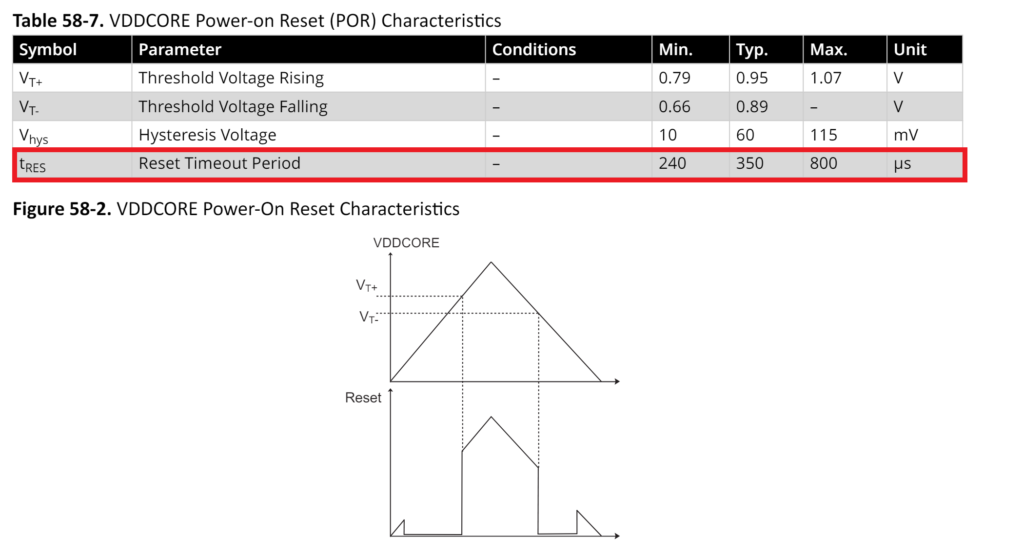
In the electrical characteristics for SAM E70 figure above shows that the reset will be held for 240-800us long, and as known in most microcontrollers, after releasing the Reset the code will run. Therefore, the security bit should be loaded before running the code. It is always a good idea to read the booting process and the timing of releasing the Reset to know exactly when the code will start to run. More into the booting process in part 2 of this series.
After setting the setup we start to capture the Power-On of the SAM E70, which is the startup shown below
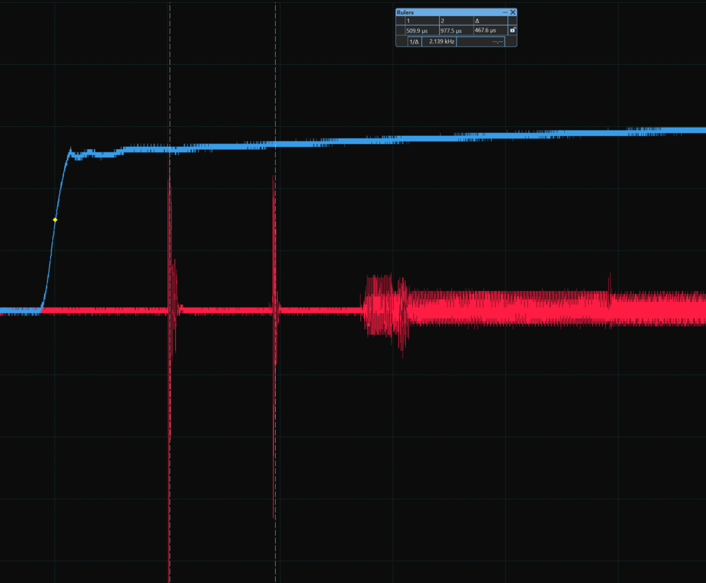
The blue trace is the trigger on the SAM 3.3v, the red trace is power of the VDDCORE. As we can see the first spikes on the VDDCORE are related to powering up the core, and after ~400us we have another spike which we think is related to the flash controller (EEFC) which where the security bit configured.
The plan is to capture the same traces 25 times then average them while the security bit is disabled, then do it all again while the security bit is enabled. Recapture and average the traces will help us eliminate the jitters.
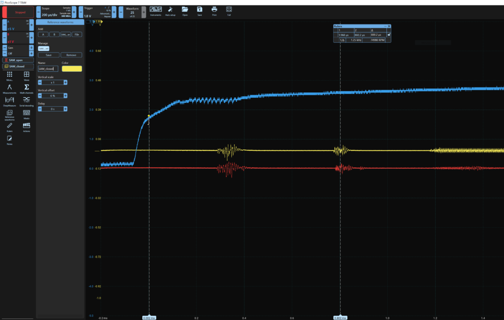
Here we can see that the blue trace is the trigger of the SAM 3.3v, the yellow trace is an average of 25 traces while the SAM is security bit enabled, also it’s vertically shifted. The red trace is an average of 25 traces while the SAM is security bit disabled. Now let’s see if we lay the traces on each other and see if there is a difference.
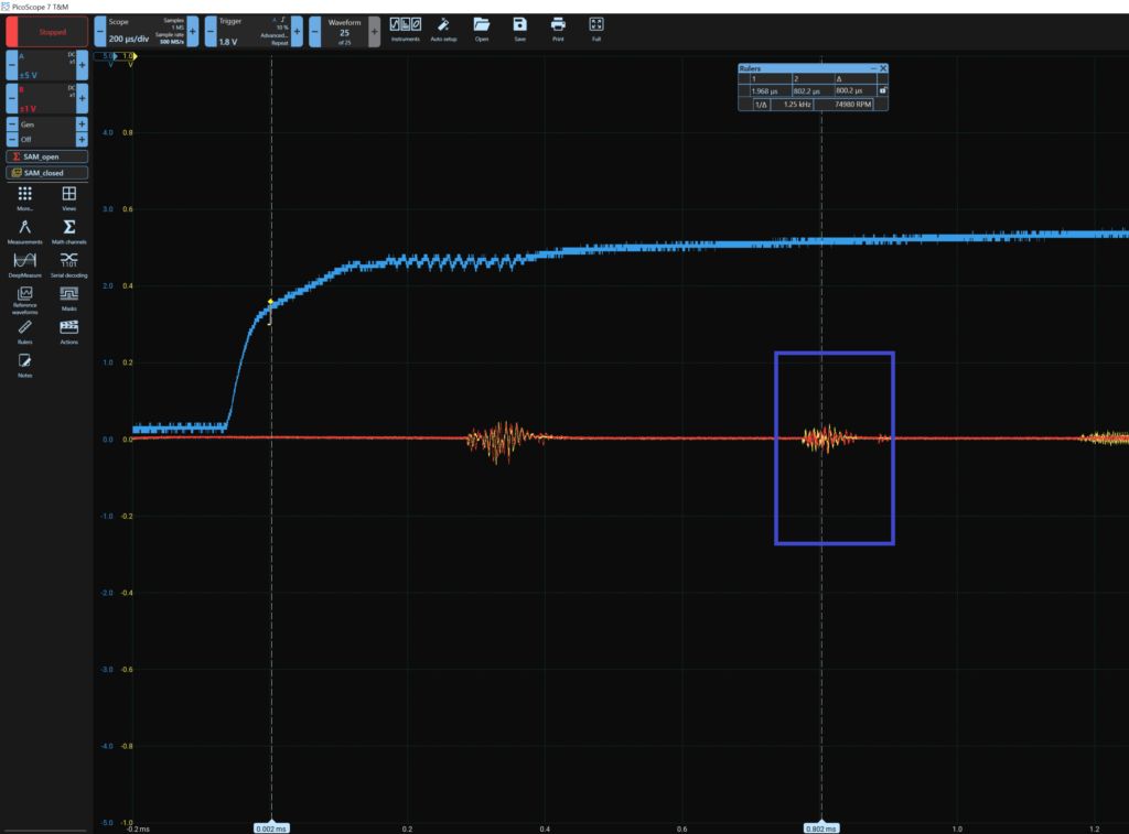
Remember we are focusing on the second spike as shown above highlighted with blue rectangle. And yes indeed there is a difference between the security bit enabled and disabled traces. Therefor, we know where is the security bit is affecting, and from that we will move to the next section.
Taking Advantage From Power Analysis (The Attack)
The goal is to bypass the security bit and take full control of the SAM, to do that we will try and corrupt the area where the security bit is effecting. We will perform a voltage fault injection using Chipwhisperer, which is a tool capable of preforming side channel and fault injection attacks.
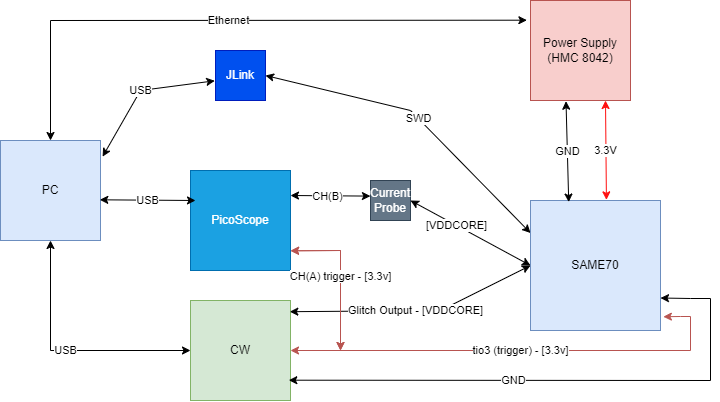
From the diagram above:
- PC: To run the exploit code and observe the power analysis.
- Power Supply (HMC 8042): Where it will Power On/Off the SAM board.
- JLink: A debug tool to check whither we have access to the SAM or not.
- PicoScope: The oscilloscope.
- Chipwhisperer (CW): The tool to preform the voltage fault injection.
The attack could be done without the oscilloscope. However, it always nice to see the glitches ⚡.
Then we wrote the code as follows:
- Configure the Power supply, JLink, and CW
- Write a function to check the debug port of the SAM from JLink
- Enter the Offset, which is a variable needed from the CW and it is the time to wait after the trigger to glitch.
- The Repeat is a range from (140-200), which is also a variable needed from the CW and it is the duration of the glitch.
- Power Off the SAM from the power supply.
- Arm the CW (Be ready for the trigger, which is the 3.3v of the SAM).
- Power On the SAM from the power supply.
- In this time the glitch will happen, then we check on the debugging port of the SAM if it opened or not.
The Offset in our case will be from 80000-90000 (800us-900us) the CW clock configured at 100MHz. The Offset in that range because our trigger is on the 3.3v not the VDDCORE. That’s another reason to use an oscilloscope while glitching at least in the begging of the setup.
The Repeat is range in our case which is 140 to 200 that is the range that we found is very suitable for the SAM.
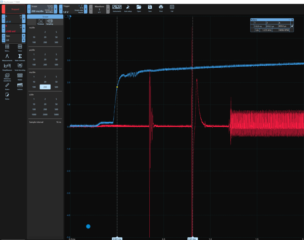
As we can see above the glitch happened at ~800us and it was a successful glitch!
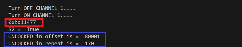
After a successful glitch it showed the debugging core ID (red rectangle) and now the debugging port is open while the security bit in enabled. You could dump the flash, control all the peripherals, access the SRAM, and have full control.
Conclusion
To conclude, Atmel SAM has implemented a security mechanism that can lock the microcontroller and disable any access, preventing against reading the firmware (the code) and reverse engineering it, or have any kind of control. However, by observing the difference between security enabled and disabled power analysis, then injecting a voltage fault on the area of difference taken from the power analysis will lead to bypassing the security mechanism and have full control. This is a serious impact on the product owner intellectual property firmware or keys if implemented. The vulnerability is on the silicon level of the Atmel SAM E70/S70/V70/V71 family, therefore, it is almost imposable to patch it without hardware redesign.
Disclosure
We contacted Microchip PSIRT in 2024/2/15 and after several emails they were able to see the vulnerability and issued the CVE. Many thanks for the PSIRT team at Microchip for their professional and quick responses!
